
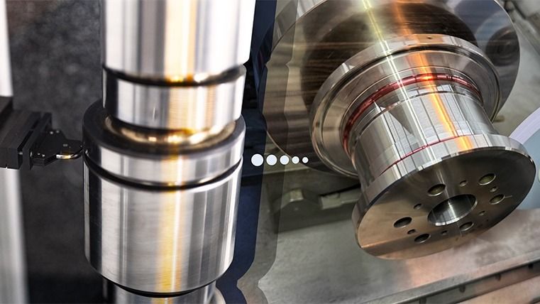
Adcole LLC’s gage writes a filtered roundness compensation file after each measurement.
Adcole LLC’s gage writes a filtered roundness compensation file after each measurement. Software averages the latest files into a single correction file sent to the grinder. Closed-loop compensation corrects small deviations continuously, and frequency-based analysis can pinpoint a UPR chatter signature before more out-of-spec parts are produced.
The gage-to-grinder loop uses filtered roundness files averaged into a single correction file for the grinding machine.
Software averages the latest files into a single correction file sent to the grinder. The compensation file is passed to the grinding machine, which applies the correction. Closed-loop compensation corrects small deviations continuously. A compensation file applies a data-driven correction consistently. Pin journal roundness compensation corrects the cross-sectional shape of a cylindrical journal.
Chatter is normally only visible after the part is already made. Frequency-based analysis lets engineers pinpoint the UPR signature tied to spindle bearing wear, wheel imbalance, or belt resonance. A compensation file can carry axis-specific, angle-specific correction data for individual journals or lobes.
Frequently asked questions
How can a closed-loop measurement-to-grinder system address common precision shaft surface problems like chatter and dimensional drift?
A closed-loop measurement-to-grinder system tackles issues like chatter and dimensional drift by providing continuous feedback. Instead of relying on manual adjustments after parts are found to be out of spec, this system measures the part immediately after grinding and generates a compensation file. This file instructs the grinding machine to adjust its parameters, such as infeed position or axis offset, for the next part or batch. This constant correction helps track gradual drifts caused by wheel wear or thermal expansion, preventing parts from moving towards or beyond tolerance limits and significantly reducing scrap.
What specific types of errors does Adcole's gage-to-grinder compensation system correct for on cylindrical journals and camshaft lobes?
Adcole's system addresses pin journal roundness by correcting the cross-sectional shape of cylindrical journals, compensating for deviations from a true circle as a function of angular position. For camshaft lobes, it corrects lobe profile errors by comparing the measured lift-versus-angle profile against nominal specifications, storing deviations as a table of error values. The grinder's CNC then uses this data to adjust the wheel position, aiming to match the designed profile more closely. In some cases, the system can also provide solutions for diameter feedback.
Beyond correcting errors, what are the key operational and financial advantages of implementing a continuous, data-driven compensation loop for grinding operations?
Implementing a continuous, data-driven compensation loop offers several advantages. It removes operator variability by applying consistent, data-backed corrections rather than relying on judgment calls. This approach protects capital equipment investment by helping qualify grinders and machining tools against a known standard, catching quality breaches early, extending the useful life of grinding wheels and dressers, and reducing unplanned downtime for full recalibration. Ultimately, it leads to reduced scrap through improved part quality and maximizes grinder uptime.
What causes chatter and lobing in precision shaft grinding, and how does this manifest in finished parts?
Chatter and lobing are caused by vibrations between the grinding wheel and the workpiece during material removal. This results in repeating, undulating patterns of marks on the shaft surface. On camshafts and crankshafts, this manifests as a periodic error with a specific number of undulations per revolution (UPR). This signature, though often invisible to the naked eye, can lead to noise, increased wear, or fatigue failures in assembled engines.
How does wheel wear and thermal growth impact the accuracy of precision shaft grinding over a production run?
As a grinding wheel wears, its diameter shrinks, altering the effective infeed and causing journal diameters, cam lobe lift, and taper to drift. This drift is gradual but accelerates as the wheel nears its dress limit. Similarly, thermal growth occurs as grinding generates heat, causing the shaft and machine components to expand. This can lead to systematic diameter or profile offsets in parts produced mid-shift, even if the machine was perfectly zeroed at the start of the day.
Why are traditional pass/fail checks insufficient for identifying surface roughness inconsistencies in precision shafts?
Traditional pass/fail checks are insufficient for surface roughness because they primarily focus on dimensional accuracy. A part can be perfectly round and within specified diameter tolerances but still exhibit inconsistent surface texture. This inconsistency often arises from variations between a new and a worn grinding wheel. Such surface finish issues affect oil retention, wear rates, and noise, vibration, and harshness (NVH) performance and cannot be detected by dimensional measurements alone.
Is this your company?
This article features your business. Claim it to add your logo, contact details, and a link to your website — or upgrade to reach more buyers.
Did you know 80% of Press Releases trigger AI content warnings? Reach out and the M4S team can assist.